
Description

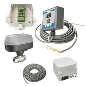
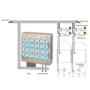
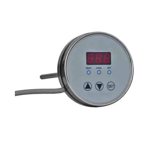
C2105 microprocessor temperature regulator is used in Breworx breweries for measuring and control of temperatures in tanks (HWT, ITWT, ICWT, CCT, OFV, BBT …). The controller cooperate with WJ500 junction box, which makes wiring easy and convenient in brewery installation and VM800 electrovalves.
The microprocessor temperature regulator C2105 is used to measure and regulate temperature. It is distinguished by:
- The ability of controlling two valves (cooling and/or heating).
- Integrated thermo sensor
- Unambiguous and simple use.
- Parametrizing at three levels (access protected with passwords, which prevents “coincidental” changes).
- Possibility of connecting into network (RS485).
- Design appropriate for humid environment and aggressive atmosphere
- Alarm for upper and lower limited.
- Simple assembly.
- It is primarily intended for the use in winegrowing, beer fermentation and maturation or other food-processing industry.
Technical data |
Values |
| Operating range | -9.9°C to 120°C (14,1°F to 248°F) |
| Resolution | 0.1°C (up to 100°F – 0.1°F; over 100°F – 1°F) |
| Accuracy | max ±0.5°C (± 0.99°F) |
| Consumption | <3W (unloaded) |
| Supply voltage | 24 V AC |
| Output for heating | max. 3A / 24V AC |
| Output for cooling | max. 3A / 24V AC |
| Connection cable | 4 m |
| Installation | in the pipe well 220 mm |
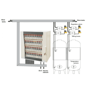
Cooling regulation (CoL)
Double jacket tanks with glycol input and output pipe connections + temperature controllers C2105 with thermometers wells + regulating valves + connecting module HSE01 + power supply adapter
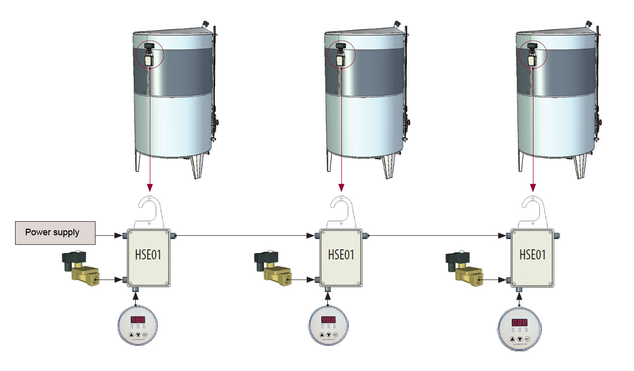
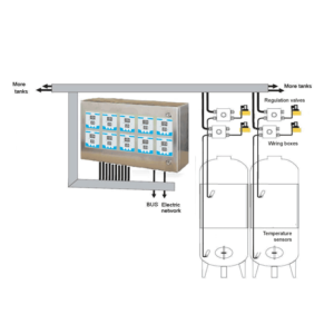
Heating regulation (HEA)
Double jacket tanks with hot water input and output pipe connections + temperature controllers C2105 with thermometers wells + regulating valves + connecting module HSE01 + power supply adapter
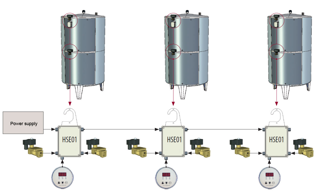
Cooling and heating regulation (H_C)
Tanks with two independent double jackets, with hot water and cold glycol input and output pipe connections + temperature controllers C2105 with thermometers wells + 2x regulating valves + connecting module HSE01 + power supply adapter
C2105 Operation manual
1. Description
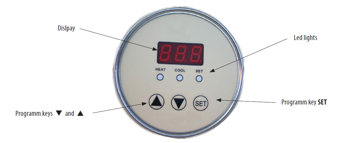
The display shows:
- Current temperature
- Setting up of parameters: set temperature, parameter or parameter value
The light shows the regulator status:
- Cooling on The red LED on
- Heating on The red LED on
- Set SP Adjustment of set temperature SP The red LED on
- unit C/F Unit C/F
- Alarm The red blinking flash
- Button [SET]
- Pressing shortly switching between the measured and the set value
- Pressing and holding change-over to the setup of regulator parameters (after entering the password)
- Pressing in the mode of parameter setup change-over to the next option 4. Buttons [▲], [▼] are used to change the regulator parameters
2. Modes
The regulator has the following modes:
- Heating and cooling regulation (output 1 heating, output 2 cooling, H_C)
- Only heating regulation (output 1 heating, output 2 disabled, HEA)
- Only cooling regulation (output 1 cooling, output 2 disabled, CoL)
- Display of the currently measured temperature (both outputs disabled, diS)
- Stand-by mode (no display of temperature, both outputs disabled, OFF)
- Adjustment of the set temperature SP
Setup of parameters 1, 2 and 3 The following abbreviations are used:
- PV measured, actual temperature, process value
- SP the desired set temperature, set point
- HsH heating hysteresis, temperature range within which output 1 does not change its status,
- HsC cooling hysteresis, temperature range within which output 2 does not change its status,
- dbd dead zone, temperature range symmetrically around the set point SP, within which neither the cooling output nor the heating output change their status
- ALU high temperature value Indicator light would be flashed when PV temperature is overran ALU value
- ALd lower temperature value Indicator light would be flashed when PV temperature is under ALU value.
- diS temperature display only, both outputs disabled
- HEA heating regulation at output 1
- CoL cooling regulation at output 1
- H_C heating regulation at output 1 and cooling at output 2
- OFF stand-by mode, both outputs disabled
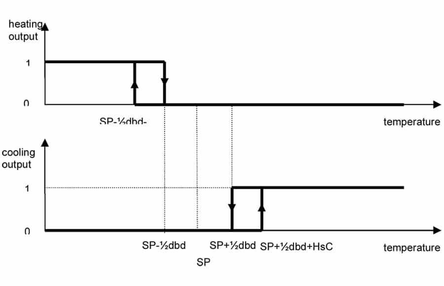
2.1 Basic mode – three-point regulator
Temperature regulator consists of output 1 for switching on the heating and output 2 for switching on the cooling. They are switched on according to the set regulator parameters. The heating output is switched on (red light is on) (the valve is opened, the heater is switched on…), when the measured (actual) temperature PV is lower than the value of SP-½dbd-HsH, and it is switched off, when the measured temperature increases above the value SP-½dbd. The cooling output is switched on (green light is on) (the valve is opened), when the measured temperature PV is higher than the value SP+½dbd+HsC, and it is switched off, when the measured temperature falls below the value SP+½dbd.
2.2 Basic mode – two-point regulator – heating
If in parameters 1 HEA is chosen, the regulator changes to two-point regulator and performs only the function of the heating regulator. Output 1 is switched on (red light is on), when the measured temperature PV is lower than the value SP-½HsH, and it is switched off, when the measured temperature PV increases above the value SP+½HsH.
2.3 Basic mode – two-point regulator – cooling

If in parameters 1 CoL is chosen, the regulator changes to two-point regulator and performs only the function of the cooling regulator. Output 1 is switched on (red light is on), when the measured temperature PV is higher than the value SP+½HsC, and it is switched off, when the measured temperature PV falls below the value SP-½HsC.

2.4 Troubleshooting
Errors in functioning are shown in the display with the following signs:
- Er.S error sensor
- Er.P error parameters
In the case of error sensor the regulator automatically switches to the ‘safe mode’. The output of heating and the output of cooling change into the status, which is preset in the parameter ‘safe mode’ SAF.
3. Adjusting the set temperature SP
The basic mode of the regulator is changed into the mode of adjusting the set temperature SP by pressing the button [SET]. During the adjustment of the set temperature yellow light is on. The value is adjusted with the buttons [▲] or [▼], and it is confirmed with the button [SET]. When the entered value is confirmed, the regulator automatically returns into the basic mode and shows the current – measured temperature.
If the selected change is not confirmed by pressing the button [SET] within 30 seconds, the value of the set temperature SP (before changing) is preserved, and the regulator returns into the basic mode – display of the current – measured temperature.
4. Regulator parameters
WARNING: Changing of parameters is permitted only to adequately trained personnel. Incorrect regulator parameters disable the functioning of the regulator.
4.1 Parameters of regulator 1
The parameters of regulator 1 define the mode of the regulator:
The parametrizing mode of regulator 1 is initiated by pressing and holding button [SET]. Then the sign “PAS” (password) is displayed. The password for parameter setup of regulator 1 is entered by pressing the buttons: ▲▲ ▼▼ and it is confirmed by pressing button [SET].
The set parameter is selected with the help of the arrow and it is enabled by pressing button [SET].
| Parameter | Description |
| OFF | stand-by, both outputs inactive |
| HEA | heating regulation at output 1 only |
| CoL | cooling regulation at output 1 only |
| H_C | heating regulation at output 1 and cooling regulation at output 2 |
| DiS | display of temperature only, both outputs disabled |
4.2 Parameters of regulator 2
The parameters of regulator 2 define the values of heating hysteresis, cooling hysteresis and dead zones.
The parametrizing mode of regulator 2 is initiated by pressing and holding button [SET]. Then the sign “PAS” (password) is displayed. The password for parameter setup of regulator 2 is entered by pressing the buttons: ▲ ▼ ▲▼, and it is confirmed by pressing button [SET].
The display first displays the name of the parameter and then its value.
Parameters are:
| Parameter name | Range | Preset | Description | ||||||||
|---|---|---|---|---|---|---|---|---|---|---|---|
| HSH | Heating hysteresis | 0.1…20 after | 1 | heating | hysteresis, | ||||||
| 0.1 | temperature | range | within | ||||||||
| which the heating output does | |||||||||||
| not change its status, heat | |||||||||||
| HSC | Cooling hysteresis | 0.1…20 after | 1 | Cooling | hysteresis, | ||||||
| 0.1 | temperature | range | within | ||||||||
| which the cooling output does | |||||||||||
| not change its status, cool | |||||||||||
| dbd | Dead zone | 0.1…20 after | 1 | dead zone, temperature range | |||||||
| 0.1 | symmetrically | around the | set | ||||||||
| value PV, within which neither | |||||||||||
| the cooling output not the | |||||||||||
| heating | output | change | their | ||||||||
| status | |||||||||||
| ALU | High temperature | -9.9~99.9°C | 99.9°C | high temperature value | |||||||
| Alarm Point value | After0.1 | Indicator light would be | |||||||||
| 14-212°F | flashed when PV temperature | ||||||||||
| After0.1 | is overran ALU value. | ||||||||||
| ALd | Low temperature | -9.9~99.9°C | -9.9°C | lower | temperature | value | |||||
| Alarm Point value | After0.1 | Indicator | light | would | be | ||||||
| 14-211°F | flashed when | PV temperature | |||||||||
| After0.1 | is under ALU value. | ||||||||||
The parametrizing mode of regulator 3 is initiated by pressing and holding button [SET]. Then the sign “PAS” (password) is displayed. The password for parameter setup of regulator 3 is entered by pressing the buttons: ▼▼ ▲▲▲, and it is confirmed by pressing button [SET]. The display first shows the name of the parameter and then its value.
Parameters are:
| Parameter name | Range | Preset | Description | |||||
|---|---|---|---|---|---|---|---|---|
| TPU | Option of measure unit | CEL | CEL | Measure unit:degree Celsius or | ||||
| of temperature C/F | FAH | Fahrenheita | ||||||
| Flt | Input filtering | 0 to 60 vz. | 5 vz. | time constant of filtering input | ||||
| signal | ||||||||
| SAF | Safe mode | noA | noA | selection of mode in case of | ||||
| CoL | error | |||||||
| HEA | noA...both outputs disabled | |||||||
| CoL...cooling output enabled | ||||||||
| HEA..heating output enabled | ||||||||
| coA | communication address | 1 to 999 | 1 | regulator address | ||||
| tSt | test calibration selector | InI | InI | Resetting parameters to preset | ||||
| values | ||||||||
| EE | EE.....eprom test | |||||||
| Cor | Cor .temperature adjust value | |||||||
| End | End...exit by entering | |||||||
| parameters | ||||||||
- InI – resets all the parameters to the initial, preset values.
- EE tests eprom. After the test the display shows:
- EGd – eprom functioning normally
- Bad – eprom corrupt
5. Technical data of the regulator:
- Display of value: -9.9°C to 99.9°C or 14.1~211℉
- Resolution: 0.1°C(to 100°F IS 0.1°F ;Over 100°F is 1℉)
- Deviation: max ± 0.5°C(±0.99°F)
- Consumption: <3W (unloaded)
- Supply voltage: 24 V AC
- Output 1 for heating: 3A 24VAC (relay)
- Output 2 for cooling: 3A 24VAC (relay)
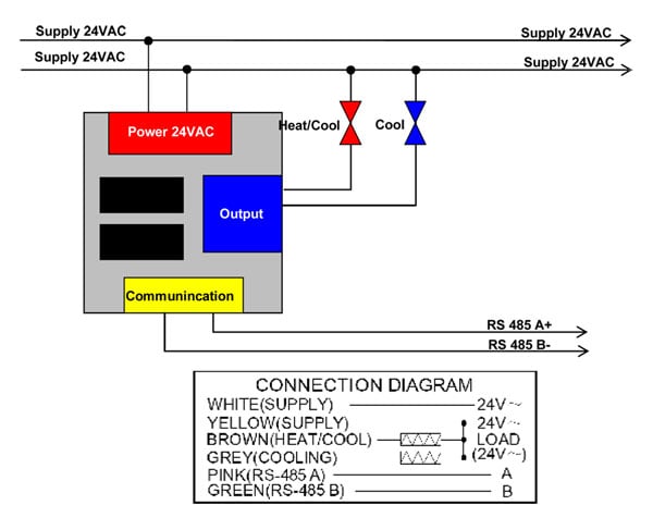
6. Scheme of connections