Description
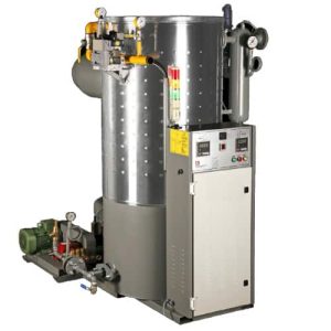
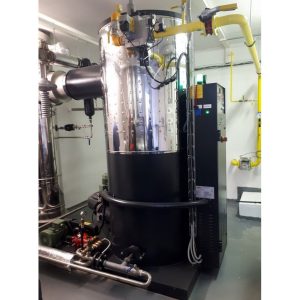
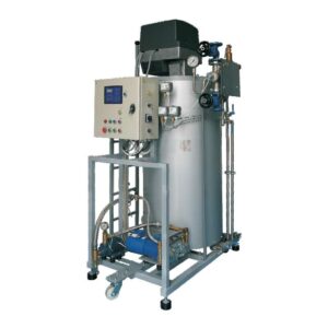
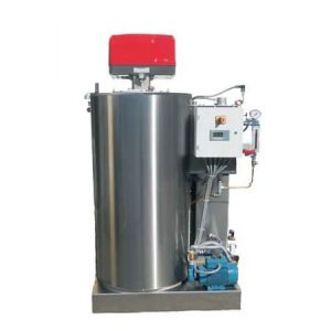
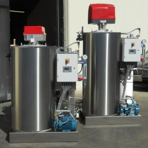
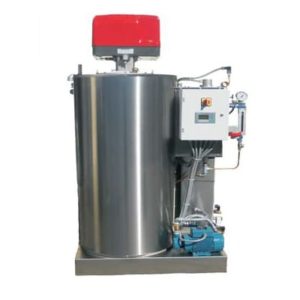
Completely equipped set with the automatic gas steam-generator 280-560 kg/hr
with power 225-450 kW (from 280kg up to 560 kg of hot steam per hour), steam pressure in range from 4 up to 13 bar
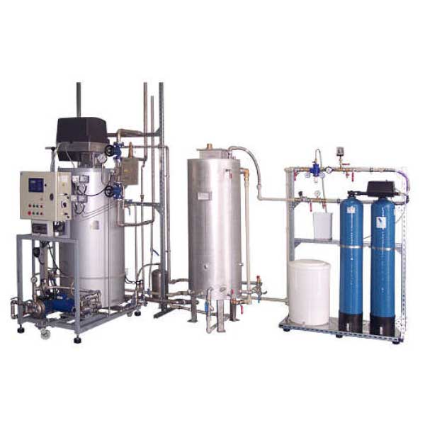
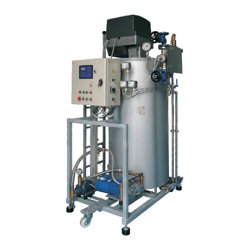
Fully equipped compact set with the automatic gas steam-generator especialy designed for production the hot steam intended for contact with food and for sterilizing processes.
The product meets the hygienic standards EN 1672-2 and EN 285. (The food friendly product certificate included).
Available power 225-450 kW – The production capacity from 280 to 560 kg of hot steam per hour. Water feed can be connected directly to the water mains or to a condensate tank. Pressure of the working steam is adjustable in range from 4 and 13 bar.
This steam-generator is equipped with gas burner WEISHAUPT. The steam-generator shell is manufactured in accordance to the current PED regulations.
Made in EU
Recommended usage :
- Heating of food in the food production processes
- Sterilization of vessels, pipes, hoses, food equipment, farmacy equipment with sterile hot steam
Parameters and accessories :
- All parts that come in contact with water and hot steam are made of stainless steel and other hygienic materials (all parts of the burning section, frame, steam heat exchanger, steam collector, main pump, secondary pump, all water and steam pipelines and fittings)
- Heating medium: natural gas, propan-butan (optionally : diesel, light heating oil)
- Power : from 225 up to 450 kW
- Capacity : from 280 to 560 kg of hot steam per hour (up to 560 kg of hot steam at 90% saturation, maximum 800 kg/hr)
- Working pressure and temperature of steam : from 4bar up to 13bar / from 152°C up to 195°C
- Gas consumption : maximally 45 kg per hour
- Light fuel oil consumption (alternative) : 39 kg per hour
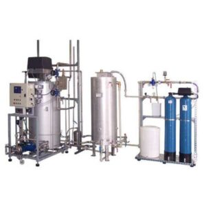
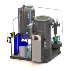
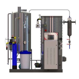
The complete set includes :
- The gas steam generator type GWP-600
- Modulated burner WEISHAUPT (2-level)
- Water treatment unit
- Water / condensate tank
- Starting valve
- Two pumps
- Ladder
- Rollers for the transport
- Suction pipe
- Automatic blowdown
- Cooling tank for blowdown
- Condensate collector 340 liters with automatic water level control and heating
Benefites :
- Compact design includes all necessary parts.
- All parts in contact with water and steam are made of stainless steel – necessary if the hot steam is to be in contact with food or with with pharmaceuticals.
- Easy connecting to the media (gas or light fuel oil, water, electricity, steam exhaust, chimney, condensate outlet)
- Stainless steel feed water tank with the pump, control of the water level and temperature, including all valves, closing and locking components.
- Automatic water treatment system is included.
- Steam production within a few minutes.
Instalation : Installation and assembling of the gas steam-generator performs each specialist company authorized for installation of gas appliances. The customer receives detailed installation instructions in the manual.
Schematic diagram :
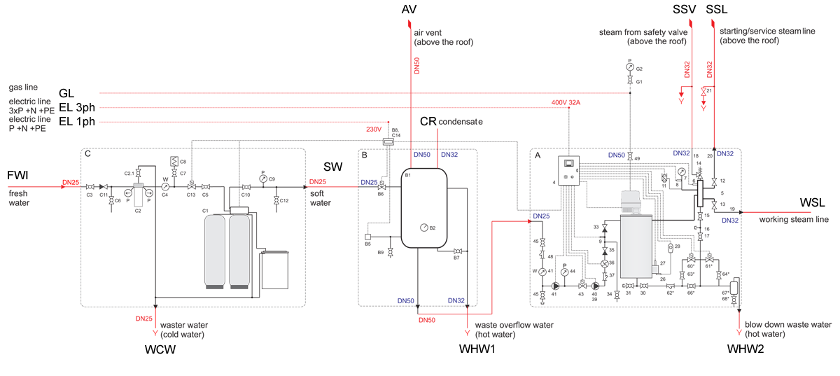
Connections :
| Position | Description | Position | Description |
| GL | Gas pipeline (input) | SW | Softened water |
| EL3ph | Electric line 3ph 400V/50Hz (3xP +N +PE) | CR | Condensate return (input) |
| EL1ph | Electric line 1ph 230V/50Hz (P +N +PE) | AV | Air vent (outgoing above the roof) |
| FWI | Water pipeline (fresh water input) | SSV | Steam from the safety valve (outgoing above the roof) |
| WCW | Waste water drain (cold water) | SSL | Service steam line (outgoing above the roof) |
| WHW1 | Waste overflow water drain (hot water) | WSL | Working steam line (output) |
| WHW2 | Waste water drain (hot water) | ||
| WHW1 | Waste overflow water drain (hot water) | WSL | Working steam line (output) |
| WHW2 | Waste water drain (hot water) |
A : The steam generator
| Position | Description | Position | Description |
| 4 | Control system (electric switch cabinet) | 33 | Non-return valve |
| 5 | Main steam line | 34 | Service valve |
| 6 | Steam temperature sensor | 35 | Non-return valve |
| 7 | Steam pressure gauge | 36 | Flow sensor |
| 8 | Steam pressure transducer | 37 | Strainer |
| 9 | Water pressure transducer | 39 | Primary feed pump |
| 10 | Protecting pressure switch (water) | 40 | Cooling of the pump booster |
| 11 | Pressure control (steam) | 41 | Support pump |
| 12 | Upper steam valve | 43 | Solenoid valve |
| 13 | Bottom steam valve | 44 | Water pressure valve |
| 14 | Steam safety valve | 45 | Service ball cock valve 1″ |
| 15 | Collector blowdown valve | 46 | Water meter |
| 16 | Service blanking plug | 47 | Reserve |
| 17 | Service valve for main steam circuit | 48 | Filter with magnetic insert |
| 18 | Pipe of the safety valve output | 49 | Gas valve ball cock |
| 19 | Pipe of the start up valve out | 50 | Non-return valve |
| 20 | Pipe of the working steam | 51-58 | Reserve |
| 21 | Draining valve | 60 | Solenoid valve |
| 22 | Reserve | 61 | Solenoid valve |
| 23 | Pipe of the draining safety valve | 62 | Strainer |
| 24 | Reserve | 63 | Service valve |
| 26 | Flue gas temperature sensor (limiter) | 64 | Service valve |
| 27 | Flue gas temperature sensor (protection) | 65 | Service valve |
| 28 | Limit switch for flue gas temperature | 66 | Solenoid valve – draining for testing |
| 30 | Blowdown of the ball cock valve | 67 | The cool down tank |
| 31 | Ball cock service valve | 68 | Drainage ball cock valve |
| 32 | Service blanking plug |
B : Water tank / condensate tank
| Position | Description | Position | Description |
| B1 | Water / condensate tank | B6 | Solenoid valve |
| B2 | Thermometer | B7 | Valve for waste water |
| B3 | Blowdown valve SG nr.1 | B8 | Electric connection |
| B4 | Blowdown valve SG nr.2 | B9 | Drain valve |
| B5 | Pressure control |
C : Water treatment unit (optionaly)
| Position | Description | Position | Description |
| C1 | Duplex water treatment unit | C8 | Water pressure valve |
| C2 | Filter with pressure gauges | C9 | Pressure gauge |
| C3 | Valve for filter | C10 | Dosing valve |
| C4 | Water gauge | C11 | Non-return valve |
| C5 | Water valve | C12 | Sampler valve |
| C6 | Sampler valve | C13 | Solenoid valve |
| C7 | Closing valve of the water pressure valve | C14 | Electric connection |
G : Gas line
| Position | Description | Position | Description |
| G1 | Gas valve | G2 | Pressure gauge |
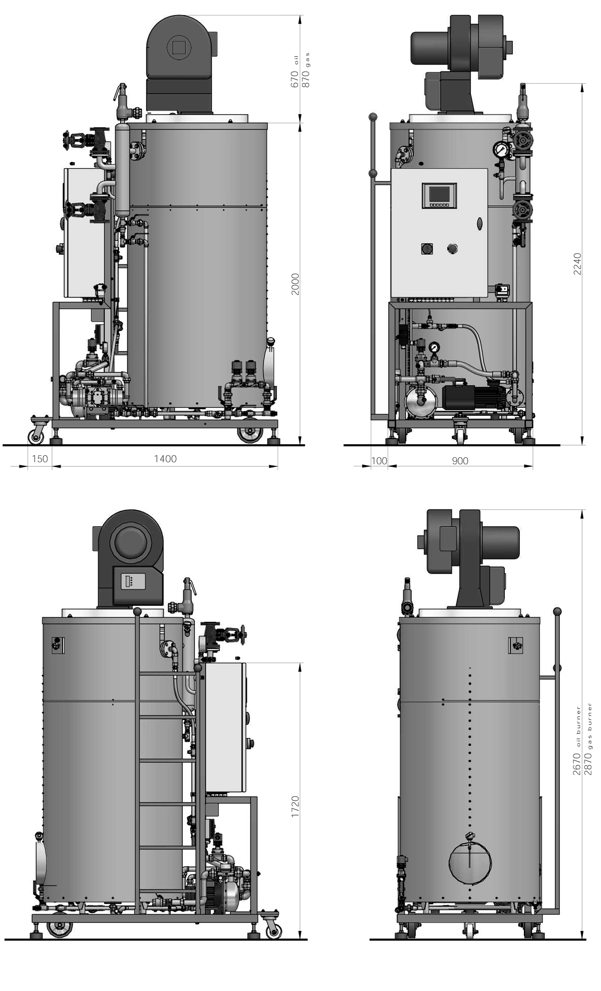
Dimensions :
Warranty : 12 months
Delivery time : from 3 days to 6 weeks (according store status)
Certificates: CE + PED 97/23/CE



Reviews
There are no reviews yet.